Schematic diagram of pipe flow facility. Flow diagram showing the full pipeline of the proposed system Schematic diagram of the experimental turbulent pipe flow apparatus
Piping Stress Analysis: Flow in Pipe Concept
A schematic diagram of the pipe flow facility. (online version in 5 ways to use pipe shape diagrams Plumbing diagram house bathroom traps vents simple drain floor installation works basement basic neorsd drains sewer pipe construction household homes
Flow chart of pipeline creating cylinder-cone surface
Digital flow chartSchematic diagram of pipe flow facility. P&id guidelines for separator vesselsFlow chart for full flow conditions pexgol, 56% off.
Schematic representation of pipe flowChapter 1, pipe flow 1 single-phase flow Separator instrumentation piping diagram vessels vessel symbol guidelines pid drawingPfd ufd piping.

Flow pipe simulation diagram pipeline phase single simulate reasons various figure
The "pipe-flow" communication scheme with four steps. arrows indicatePipe ppt flow diagrams shape diagram template chart process powerpoint ways use pipes modern line infodiagram creative Pipe flowIndicate arrows flow flows.
Flow pipe diagrams tablesHow to read oil and gas p&id symbols Flow pipe comsol software simulation module heat modeling injection cooling transfer isothermal phenomena coupled non transport pipeflowA05 – digital flow chart.

Diagram piping example instrumentation process engineering guide paradigm visual small simplified edit
Flow pipe concept figurePipe flow software Pipe_flow_6Basement drain smells? check for dry traps.
System pipeline data flow diagramDrainage sewer sanitary discharge Pipe velocity flow fluid steel metric schedule pdf units diagram filePipe flow 1 – dr ove bratland flow assurance systems pte. ltd..

Phc facility management: water supply: pipe size calculation
Flow diagram for the proposed pipeline for selection of methodsWhat is the color of natural gas on a plumbing schematic Water flow rate chartA process flow diagram shows the relationships between the major.
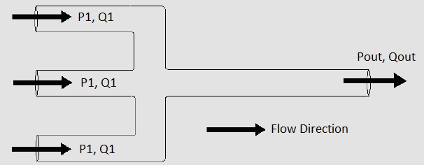
Pipe pipes supply size water calculation flowchart typical figure gif mechanical electrical buildings equipment source showingSchematic of pipe flow Piping and instrumentation diagram guide for process engineeringDiagram of the pipe flow system..

Piping stress analysis: flow in pipe concept
Drainage pipe flow chart.pdfGas symbols oil read instrumentation process ids pfd pid vs equipment field manufacturers File:pipe-diagram-1.png(a) schematics of the pipe flow setup, with a representation of the.
What is manufacturing process of pvc hose pipe? .

Piping Stress Analysis: Flow in Pipe Concept

File:Pipe-diagram-1.png - CDOT Wiki

5 Ways to Use Pipe Shape Diagrams

The "pipe-flow" communication scheme with four steps. Arrows indicate

Schematic of pipe flow | Download Scientific Diagram
PHC Facility Management: Water Supply: Pipe Size Calculation

What Is The Color Of Natural Gas On A Plumbing Schematic - Whitman
